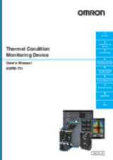
K6PM-TH
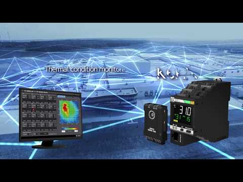
Thermography-based Condition Monitoring
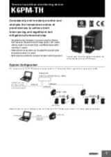
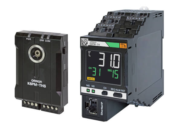
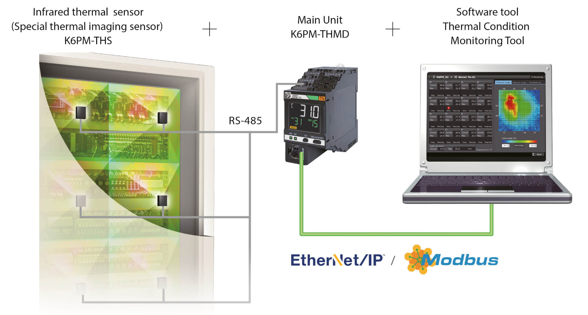
K6PM-TH measures and monitor the surface temperature through up to 31 connected infra-red cameras, as a continuous thermography.
- Monitor and predict temperature trend, signalling alarm anytime the temperature of a given area is above the set threshold or is expected to reach critical value in near future
- Consider the differential temperature trend (between environment and measured object), signalling alarms only if critical conditions occur.
- automatically set the temperature threshold of each area (every camera divides the monitored area in 16 quadrants), based on baseline conditions
- E-mail notifications in case of warning/alarm,
- Remote monitoring
- Interaction with custom applications and MQTT server.
Specifications & ordering info
| Product | Supply voltage AC | Supply voltage DC | Description | |
|---|---|---|---|---|
|
|
20.4-26.4 V | 20.4-26.4 V | Thermal condition monitoring device for control cabinets and panels, 24 VDC, transistor control output, Push-in Plus, LCD display, EtherNet/IP and Modbus TCP |
|
Need assistance?
We’re here to help! Reach out, and our specialists will assist you in finding the best solution for your business.
Contact Our Experts K6PM-TH

Thank you for submitting your request. We will come back to you as soon as possible.
We are experiencing technical difficulties. Your form submission has not been successful. Please accept our apologies and try again later. Details: [details]
DownloadQuotation for K6PM-TH
By completing this form you can request a quotation. Your personal details will be handled confidentially.
Thank you for requesting a quotation. We will provide you with the required information as soon as possible.
We are experiencing technical difficulties. Your form submission has not been successful. Please accept our apologies and try again later. Details: [details]
DownloadFeature
K6PM is a reliable partner to monitor critical facility panels, as well as equipment panels along their entire life (development, validation, FAT and after installation).
Particularly suitable for those application where the panel is located right next to a machine generating intensive heat (furnaces, ovens, molding machinery).
Condition monitoring devices can be configured with a single tool
Easy three-step configuration The Condition Monitoring Configuration Tool allows for batch configuration of a wide range of condition monitoring devices, such as those for monitoring motors, temperatures, insulation, and heaters. It can be used without any special skills, reducing training effort
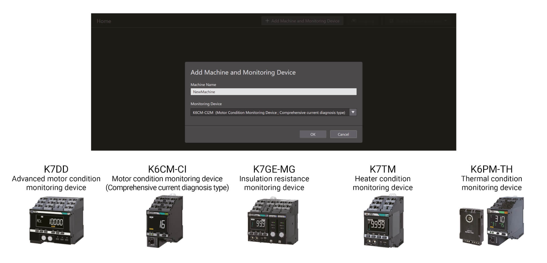
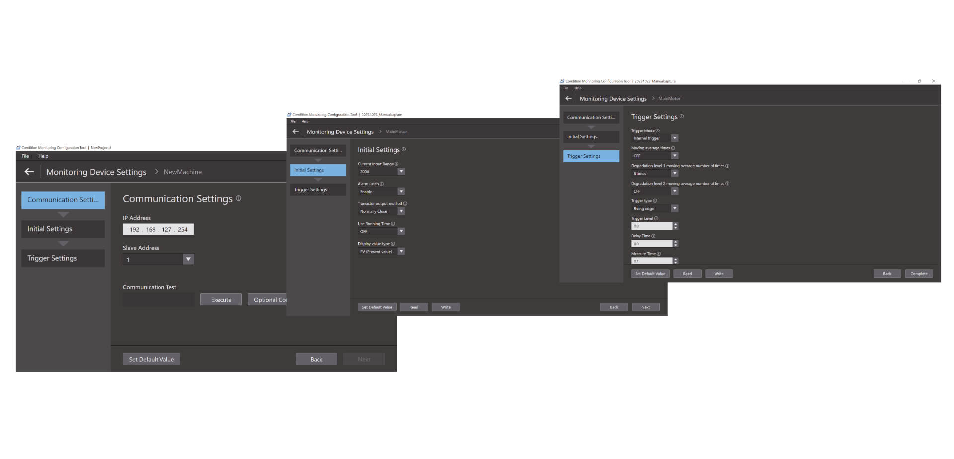
Easy three-step configuration
The Condition Monitoring Configuration Tool allows for batch configuration of a wide range of condition monitoring devices, such as those for monitoring motors, temperatures, insulation, and heaters. It can be used without any special skills, reducing training effort. Setup can be completed in just three steps: communications setup, initial setup, and trigger setup.*1 With its high operability, the tool boosts on-site productivity as well.
Videos
-
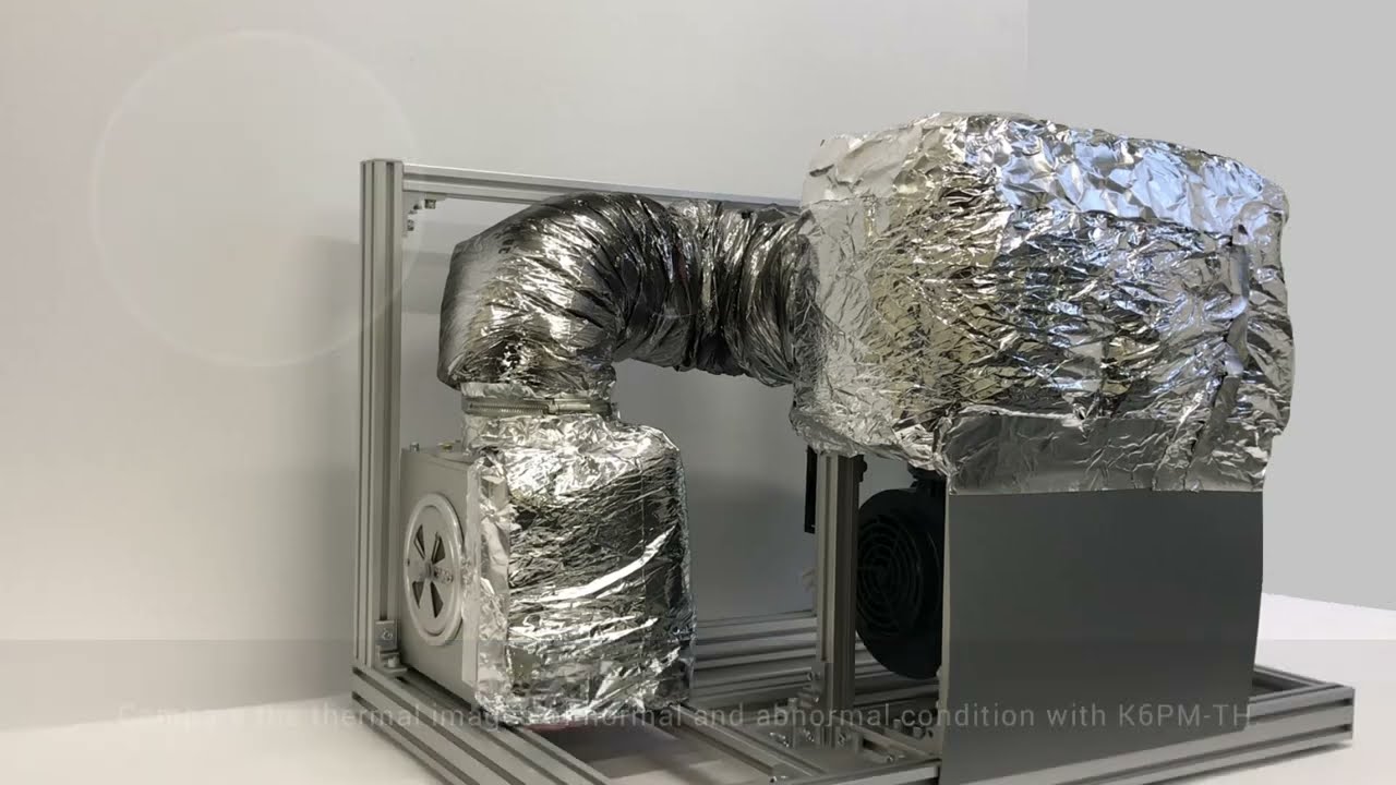
OMRON K6PM-TH Thermal Condition Monitor Detecting Dryer Duct Leak
Coating and drying is one of the most dangerous processes in car manufacturing. In the drying oven, air heated to 400°C in the combustion chamber travels through the air duct for use in drying. These air ducts degrade over time, sometimes allowing air hotter than 100°C to leak, which can lead to burn injuries during patrol inspection. #omronindustrialautomation #MakeitOMRON
02:59
OMRON K6PM-TH Thermal Condition Monitor Detecting Dryer Duct Leak
Coating and drying is one of the most dangerous processes in car manufacturing. In the drying oven, air heated to 400°C in the combustion chamber travels through the air duct for use in drying. These air ducts degrade over time, sometimes allowing air hotter than 100°C to leak, which can lead to burn injuries during patrol inspection. #omronindustrialautomation #MakeitOMRON
-
K6PM: Innovation in thermal monitoring and panel maintenance
Parts to check are increasing as devices and wires in a panel increase for high-functioned facilities and equipment. On the other hand, maintenance frequency is decreasing due to shortage of the maintenance engineers, resulting in a higher risk of accident. There are various causes of failures on the device. Current methods of manual inspections are useful but they only provide limited amount of failure detection information. Here is a new solution from OMRON.
02:37
K6PM: Innovation in thermal monitoring and panel maintenance
Parts to check are increasing as devices and wires in a panel increase for high-functioned facilities and equipment. On the other hand, maintenance frequency is decreasing due to shortage of the maintenance engineers, resulting in a higher risk of accident. There are various causes of failures on the device. Current methods of manual inspections are useful but they only provide limited amount of failure detection information. Here is a new solution from OMRON.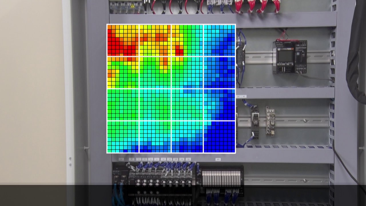
-

Omron K6PM "Auto threshold set" algorithm
The amount of heat generated varies from device to device. For this reason, the optimum threshold value for the thermal monitoring must be set depending on the device. K6PM can divide one sensor monitoring area into 16 segments and automatically set the threshold for each segment.
01:27
Omron K6PM "Auto threshold set" algorithm
The amount of heat generated varies from device to device. For this reason, the optimum threshold value for the thermal monitoring must be set depending on the device. K6PM can divide one sensor monitoring area into 16 segments and automatically set the threshold for each segment.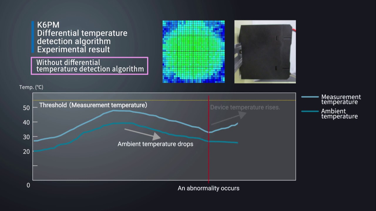
-

Omron K6PM "Differential temperature detection" algorithm
For applications where there are fluctuations in ambient temperature, it can be difficult to determine the cause of the temperature change of the device. The K6PM constantly monitors the difference between measure temperature and ambient temperature. This allows the K6PM to accurately detect abnormalities without being affected by ambient temperatures.
01:51
Omron K6PM "Differential temperature detection" algorithm
For applications where there are fluctuations in ambient temperature, it can be difficult to determine the cause of the temperature change of the device. The K6PM constantly monitors the difference between measure temperature and ambient temperature. This allows the K6PM to accurately detect abnormalities without being affected by ambient temperatures.
-

Omron K6PM "Arrival prediction" algorithm
Predicts the estimated temperature value based on the temperature rise trend. With the Predictive temperature algorythm, you can quickly identify potential risks before they ccould lead failures and machine downtime. Watch a testing example.
01:52
Omron K6PM "Arrival prediction" algorithm
Predicts the estimated temperature value based on the temperature rise trend. With the Predictive temperature algorythm, you can quickly identify potential risks before they ccould lead failures and machine downtime. Watch a testing example.
-

Installation procedure of thermal image sensor (K6PM-THS) in the panel
Watch the installation video for a smooth integration of the K6PM.
02:33
Installation procedure of thermal image sensor (K6PM-THS) in the panel
Watch the installation video for a smooth integration of the K6PM.Solutions
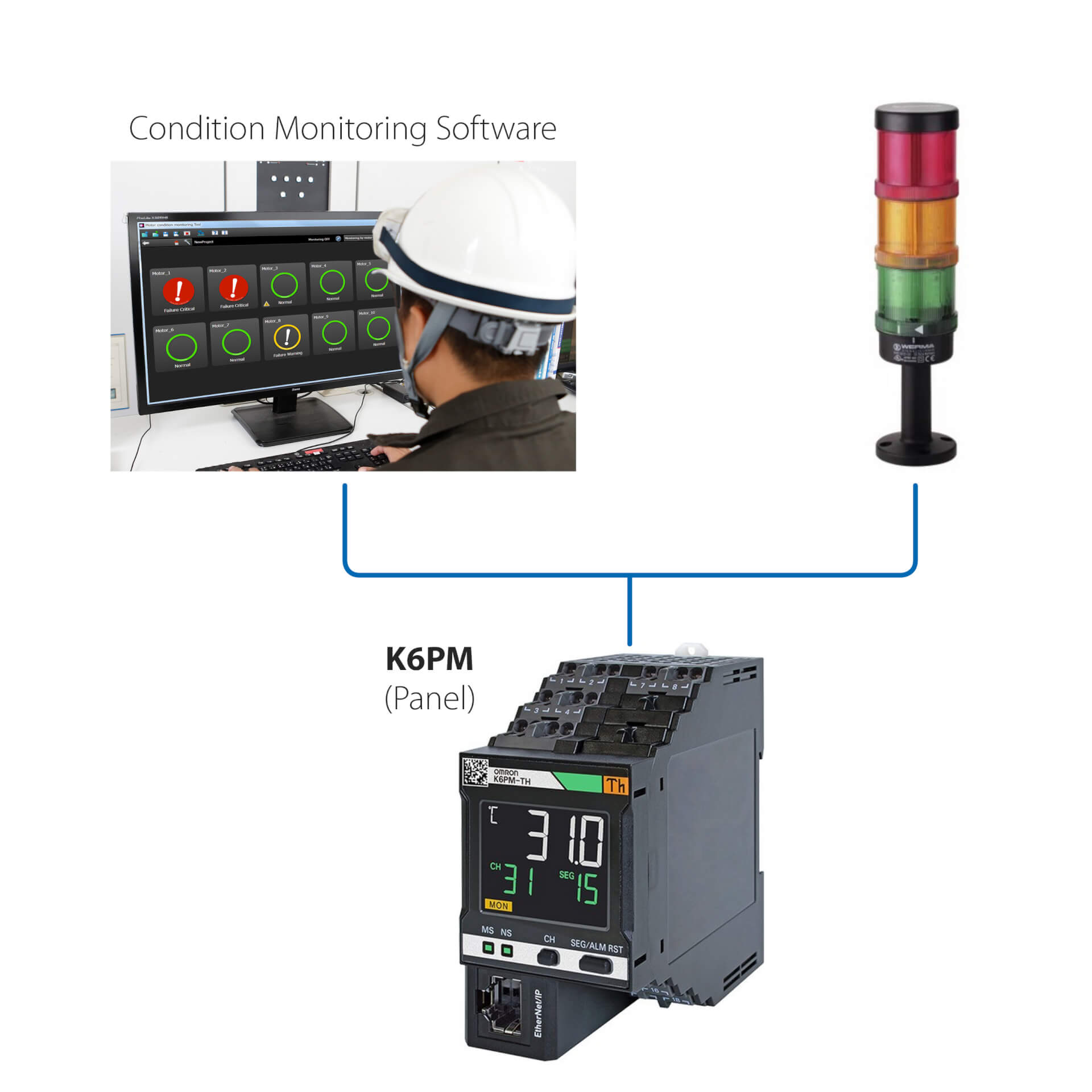
Stand Alone installation (Without PLC)
This simple solution allows to:
- Monitor the status of the motor through the onboard LED, or through to the Condition Monitoring Software
- Setup the controllers through the Condition Monitoring Software, provided with the device
- Interface the K6PM with any external I/O devices (dig. Output)
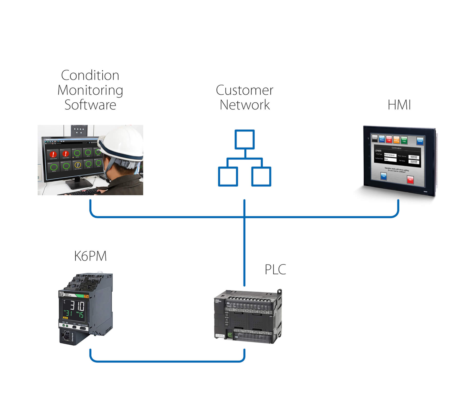
Stand Alone installation (with PLC)
This solution enables, in addition of the previous solution, to:
- Monitor the status of the motor through to the Condition Monitoring Software, running on a PC which is connected through a PLC
- Use the PLC remote-connection to reach the K6PM for remote monitoring and setup
- Trigger, through the PLC, actions following any warning/alarm detected by K6PM
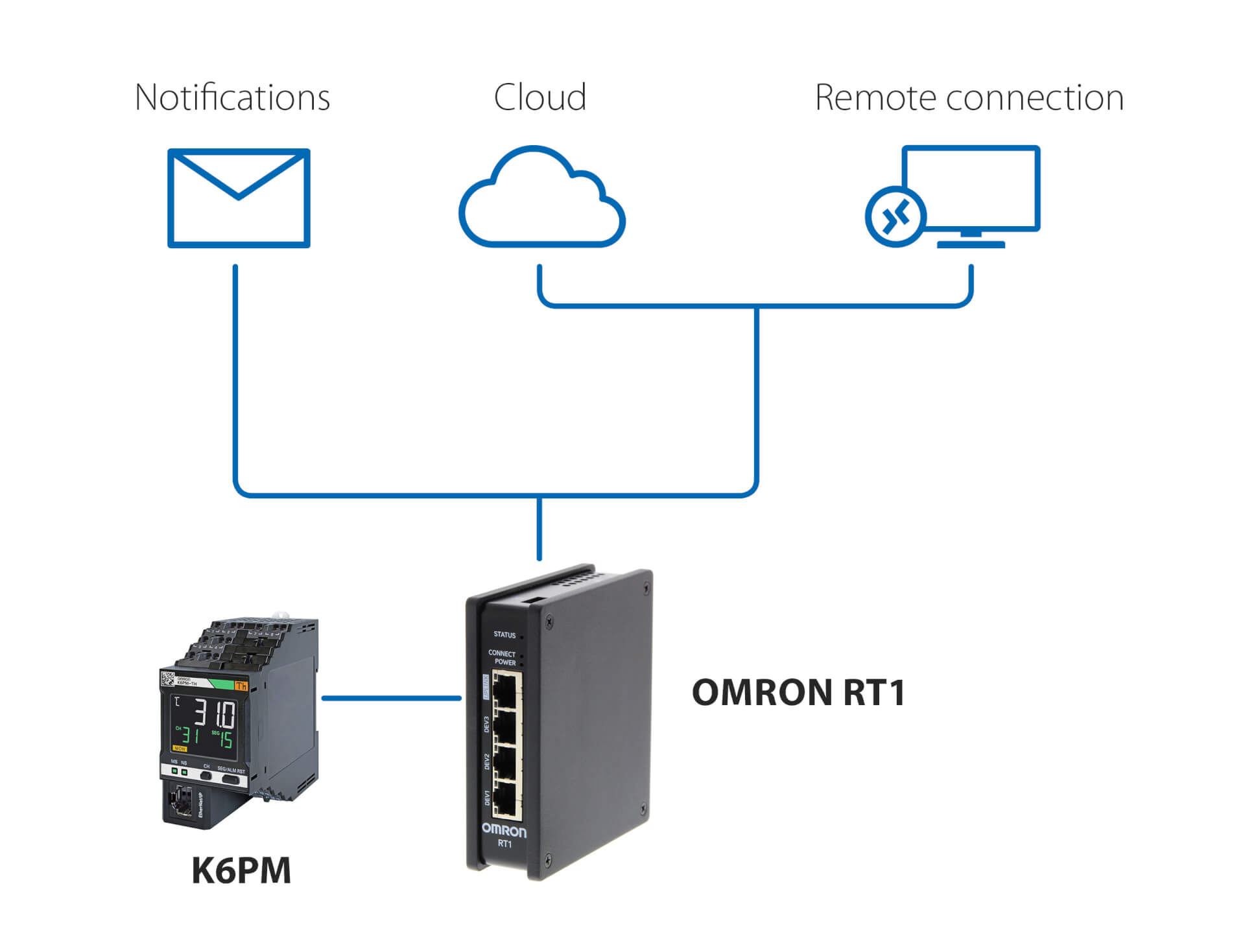
Notifications and remote monitoring - without PLC
This solution, using Omron RT1 as a gateway, enables:
- e-mail/SMS notifications in case anomalies are detected by K6PM
- secure connection (managed by RT1) to cloud, either via LAN or via 4G connection
- secure connection for remote monitoring and setup of K6PM, using the Condition Monitoring software provided with the controller
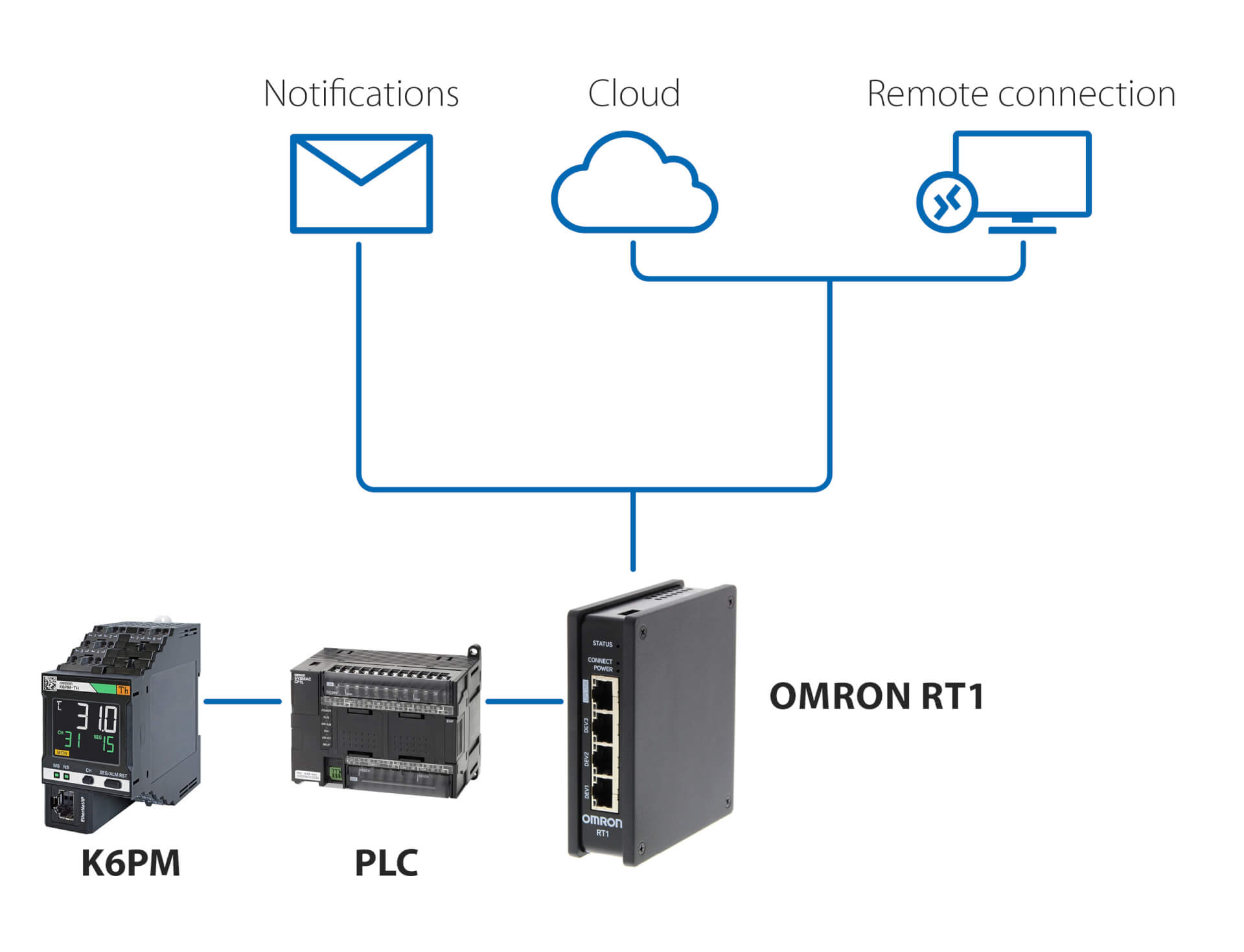
Notifications and remote monitoring – with PLC
This solution, using any PLC and Omron RT1 as a gateway, enables:
- e-mail/SMS notifications in case anomalies are detected by K6PM
- secure connection (managed by RT1) to cloud, either via LAN or via 4G connection
- secure connection for remote monitoring and setup of K6PM, using the Condition Monitoring software provided with the controller
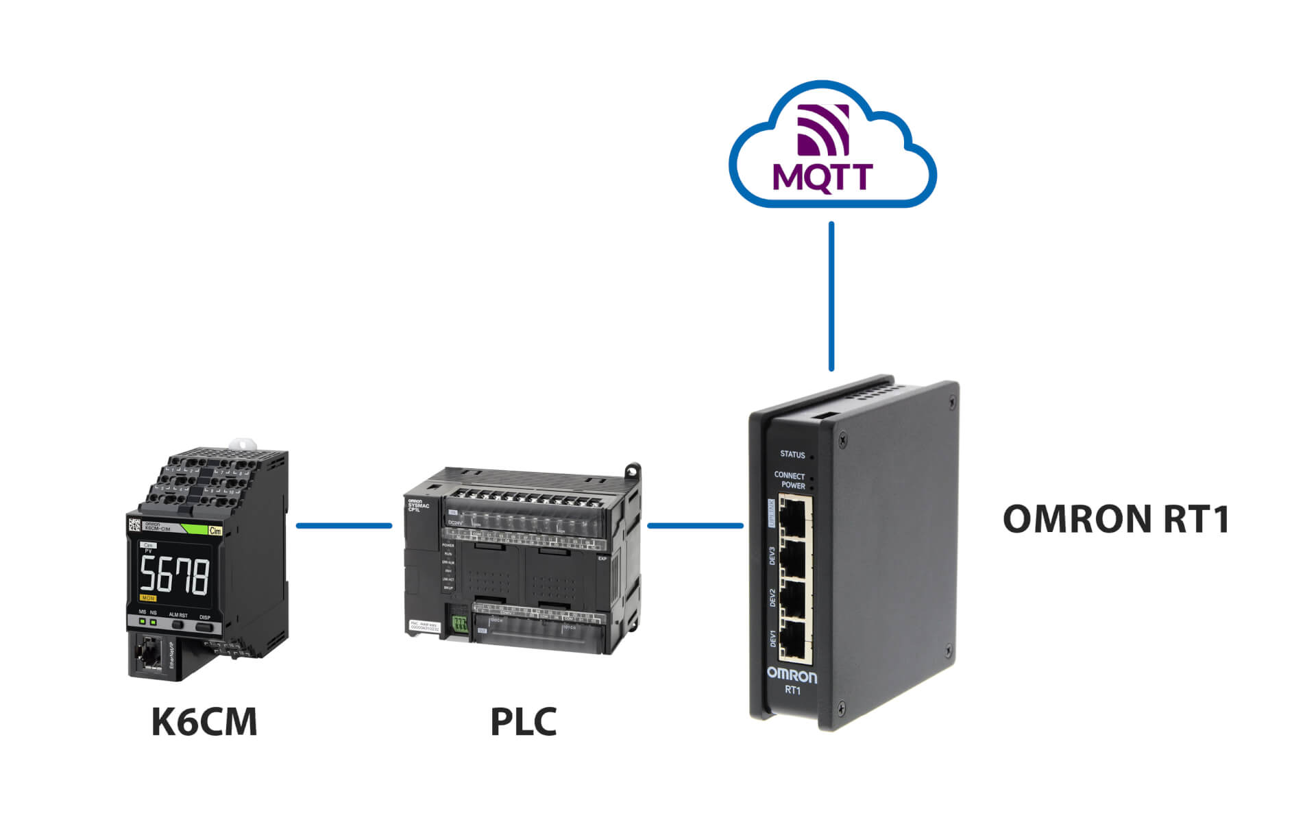
Connection to MQTT server
Related products
-
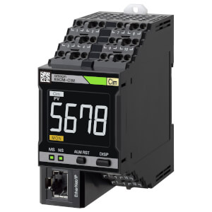
Motor Condition Monitoring Device – current monitoring
-
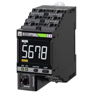
Motor Condition Monitoring Device – insulation monitoring
-
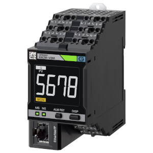
Motor Condition Monitoring Device – vibration monitoring
-
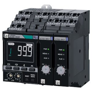
Condition Monitoring Device – insulation monitoring
Downloads