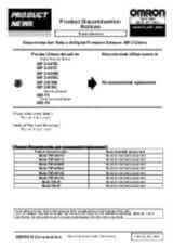
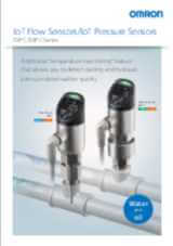
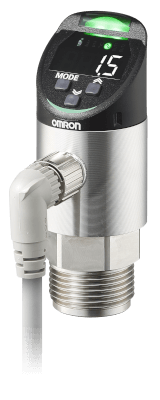
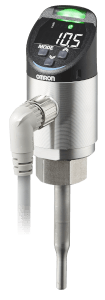
E8PC Pressure Sensors
IoT Pressure Sensors
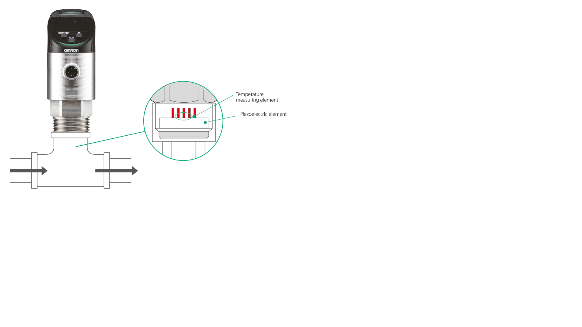
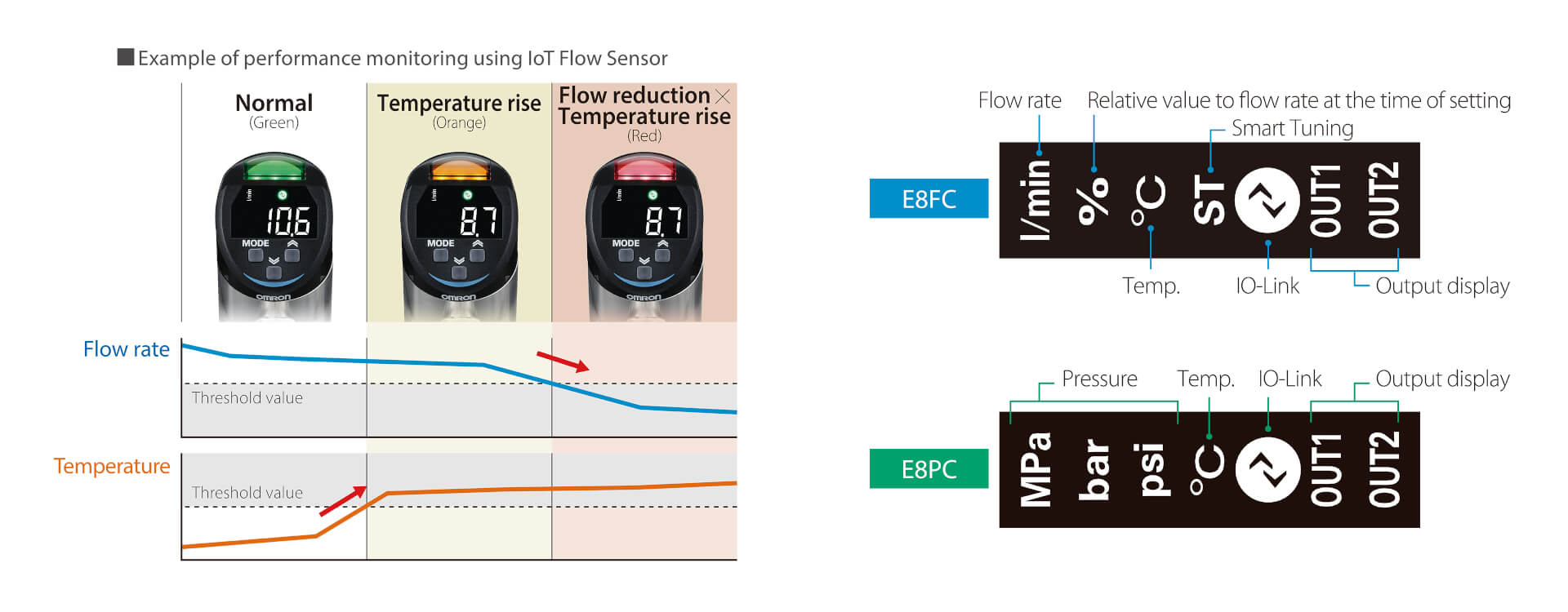
Detect signs of abnormalities by simultaneous measurement of pressure and temperature
- Multi-sensing of pressure and temperature
- Applicable for liquids and gas
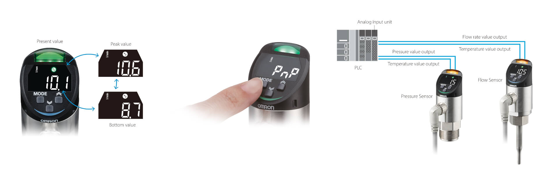
- Two-channel analog current output
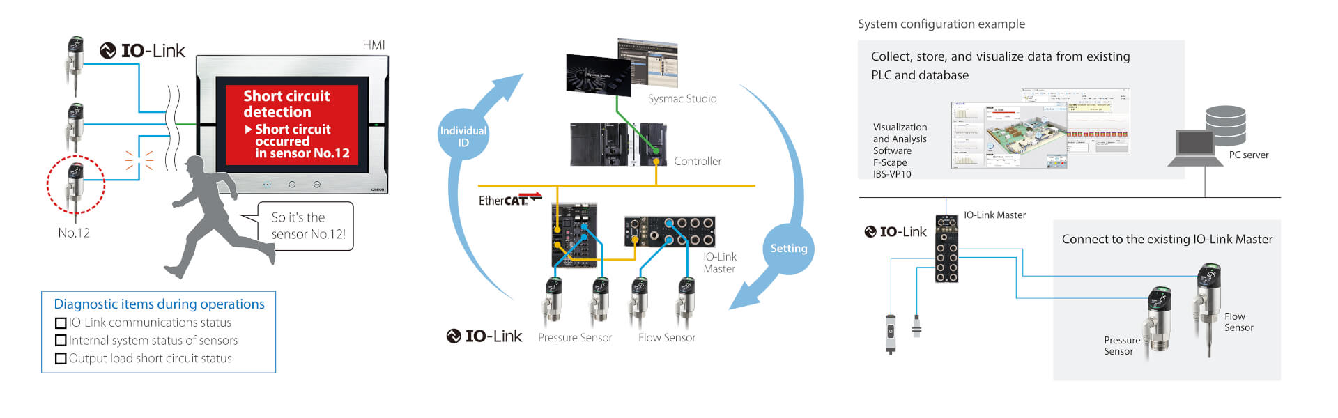
- Self-diagnostic outputs via IO-Link
- Peak/Bottom hold function
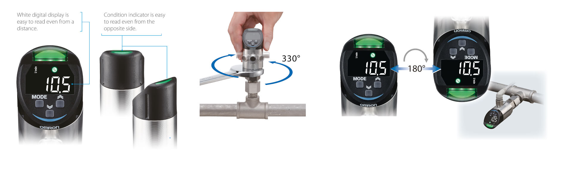
- High luminosity LED display
- Easy-to-clean structure
- Wide portfolio of adapters
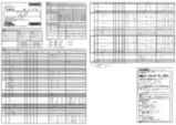
Specifications & ordering info
| Product | Application | Applicable medium | Rated pressure range | Output type | Analogue | IO-Link function | IO-Link baud rate | Description | |
|---|---|---|---|---|---|---|---|---|---|
|
|
Pressure control | Non-corrosive gas, Non-corrosive liquid | -0.1-1 MPa | IO-Link, NPN, PNP | Yes | Yes | COM3 (230.4 kbps) | Pressure sensor, liquid and gas, -0.1 to 1 MPa, PNP/NPN, IO-Link COM3, analog, M12 connector |
|
|
|
Pressure control | Non-corrosive liquid | 0-10 MPa | IO-Link, NPN, PNP | Yes | Yes | COM3 (230.4 kbps) | Pressure sensor, liquid, 0 to 10 MPa, PNP/NPN, IO-Link COM3, analog, M12 connector |
|
|
|
Pressure control | Non-corrosive liquid | 0-40 MPa | IO-Link, NPN, PNP | Yes | Yes | COM3 (230.4 kbps) | Pressure sensor, liquid, 0 to 40 MPa, PNP/NPN, IO-Link COM3, analog, M12 connector |
|
Need assistance?
We’re here to help! Reach out, and our specialists will assist you in finding the best solution for your business.
Contact Our Experts E8PC Pressure Sensors
Thank you for submitting your request. We will come back to you as soon as possible.
We are experiencing technical difficulties. Your form submission has not been successful. Please accept our apologies and try again later. Details: [details]
Quotation for E8PC Pressure Sensors
By completing this form you can request a quotation. Your personal details will be handled confidentially.
Thank you for requesting a quotation. We will provide you with the required information as soon as possible.
We are experiencing technical difficulties. Your form submission has not been successful. Please accept our apologies and try again later. Details: [details]
Features
Multi-sensing technology
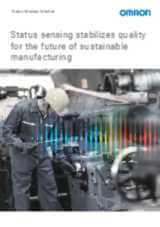
Clear and precise notifications of changes in the cooling water
Useful functions to capture equipment status
Self-diagnostic outputs, batch settings, and visualization of on-site issues
Easy-to-read digital display and adjustable angle
Related products
-
IoT Flow Sensors
-
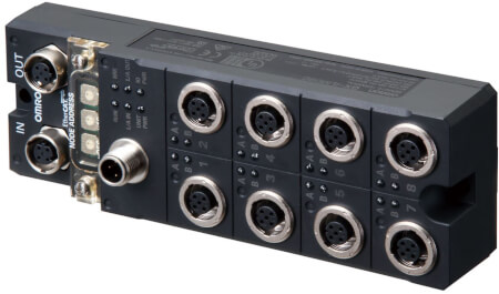
IO-Link master unit for water and dusty environments
-
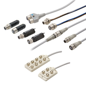
Industrial connectors & cordsets for any application
-
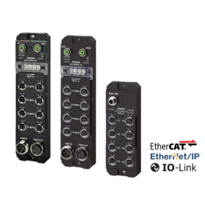
Remote IP67 IOs over Ethercat and Ethernet/IP networks with IO Link master functionality
Downloads